
In certain protective coating applications, it is vital to test the finished system for flaws and pinholes, as these defects can lead to premature coating failure in service. This is particularly important when the coating is used in an immersion or partial immersion situation such as for tank or pipe linings. The main technique used for porosity testing of protective coatings is the high voltage test where a probe with a voltage, measured in kilovolts (kV,) is applied to the coating, and detections of a flaw result in a flow of current, which can be used to create an alarm.
The two ASTM documents for porosity or discontinuity detection, D 5162 for testing coatings on a metal substrate and D 4787 for testing for coatings on concrete, both mention continuous DC and pulsed DC apparatus. The NACE recommended practice, SP 0188, also refers to these two test methods. This paper will discuss these two types of equipment and compare and contrast their use and performance.
Acceptance testing for coatings applied as protection for buried pipelines or for tanks usually includes porosity testing. Porosity testing in coatings is often referred to as holiday detection and can be carried out using either low voltage (wet sponge testing) or high voltage testing.
Holiday detection using the wet sponge method is restricted to coatings that are up to 500 μm (20 mil) thick. The wet sponge detectors will only alarm when the sponge electrode is passed over a pinhole, which penetrates right through the coating to the substrate. This method will not be discussed in this paper.
High Voltage Porosity Detection can be used to locate flaws and defects in a coating on the surface of a conductive substrate. This substrate can be metallic, steel, stainless steel, aluminum, or concrete with sufficient moisture content to make it conduct the electrical current drawn from the unit when a flaw is detected.

High Voltage Porosity Detection can be used to locate flaws and defects in a coating on the surface of a conductive substrate. This substrate can be metallic, steel, stainless steel, aluminum, or concrete with sufficient moisture content to make it conduct the electrical current drawn from the unit when a flaw is detected.
There are two main types of High Voltage Porosity Detector, the Continuous DC type and the Pulsed DC type. High Voltage AC (alternating current) Holiday Detectors are also available. These use the Tesla Coil discharge to a grounded surface to indicate the presence of a flaw by drawing the blue corona generated by the high AC voltage to the grounded substrate. However, surface contaminants and moisture content can also cause a spark and the high AC voltage is hazardous and can more easily cause severe electrical shocks in us.
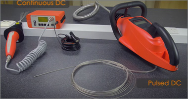
This paper will discuss the operation and use of the Continuous DC and Pulsed DC High Voltage Porosity Detectors. The difference between Pulsed DC and AC is the fact that the pulsed DC voltage changes from zero volts to the test voltage and back to zero many times per second whereas the AC voltage changes from the test voltage in both positive and negative swings at the frequency of the mains voltage 60 Hz in the USA or 50 Hz in Europe.

Coating defects will tend to reduce the life expectancy of a coating in service, particularly if the service is to include immersion, such as the lining of a pipe or a tank. There are many causes that can be attributed to coating defects and some of the more common flaws which result in porosity or holidays in a coating include runs and sags, pinholes, cratering, cissing, and the wrong coating thickness.

Runs and sags are caused by excessive local coating thickness while pinholes are often caused by air or blast media trapped in the coating during its application. Cratering is the result of air release from the surface of the coating at the point in the process where the coating is partially cured and the coating does not flow back to cover the void created by the release of the air. Cissing is also known as crawling or fisheyes and is characterized by surface breaks in the coating film revealing the substrate beneath and often results from contamination of the substrate by organic materials such as oil or grease.
| Table 1 Suggested Voltages for High-Voltage Spark Testing according to NACE SP0188 | ||
|---|---|---|
| Total Dry Film Thickness | Suggested Voltage | |
| (µm) | (mil) | (V) |
| 200 to 300 | 8 to 11 | 1,500 |
| 300 to 400 | 12 to 15 | 2,000 |
| 400 to 500 | 16 to 20 | 2,500 |
| 500 to 1,000 | 21 to 40 | 3,000 |
| 1,000 to 1,400 | 41 to 55 | 4,000 |
| 1,400 to 2,000 | 56 to 80 | 6,000 |
| 2,000 to 3,200 | 81 to 125 | 10,000 |
| 3,200 to 4,700 | 126 to 185 | 15,000 |

Many of the International Standard Societies publish standards that cover the use of high voltage holiday detectors for coatings, including NACE, ASTM and ISO. NACE – The National Association of Corrosion Engineers (NACE International) standard SP0188: 2006 “Discontinuity (Holiday). Testing of New Protective Coatings on Conductive Substrates”, provides a procedure for electrical detection of minute discontinuities in coating systems that are liquid-applied to conductive substrates other than pipelines. Section 4 of this standard describes the use of high voltage spark testing and it defines the high voltage as being in excess of 800 V. The test voltage is suggested according to the thickness of the coating in bands as shown in table 1.

NACE RP0274:2004 High Voltage Electrical Inspection of Pipeline Coatings refers to both DC and Pulsed DC detectors and defines pulse-type detectors as having high voltage pulses of very short duration, e.g. 0.0002 seconds at a rate of 30 pulses per second.
The recommendations in the standard do not apply to thin-film coatings (i.e. coating materials usually applied by a fusion bonding process. It is noted that thin-film pipeline coatings are generally applied to a dry film thickness less than 0.5 mm (20 mil).)
The determination of the test voltage is given in section 3 and shall be within 20% of the value determined from either of the equations below or from the values shown in table 2. The equations have two forms, one for thickness in metric units (mm) and one for thickness in imperial (English) units (mil) as follows:
| V = 7,900√T | ||
| Where: | V = test voltage and T is the thickness in mm | |
| V = 1,250√T | ||
| Where: | V = test voltage and T is the thickness in mil | |
| Table 2 Minimum Testing Voltage for Various Coating Thicknesses From NACE RP0274 | ||
|---|---|---|
| Coating Thickness | Testing Voltage | |
| (mm) | (mils) | (V) |
| 0.51 | 20 | 6,000 |
| 0.79 | 31 | 7,000 |
| 1.60 | 62 | 10,000 |
| 2.40 | 94 | 12,000 |
| 3.20 | 125 | 14,000 |
| 4.00 | 156 | 16,000 |
| 4.80 | 188 | 17,000 |
| 13 | 500 | 28,000 |
| 16 | 625 | 31,000 |
| 19 | 750 | 34,000 |

NACE SP0490-2007, Holiday Detection of Fusion-Bonded Epoxy External Coatings of 250 to 760 μm (10 to 30 mil) also describes both Continuous DC and Pulsed DC Holiday Detectors and also gives both formula and voltage table approach to selecting the test voltage based on the thickness of the coating.

The thickness of the coatings determines the nature of possible flaws as well as the method for their identification. While thicker coatings are required for specific purposes, it is also more prone to peeling and cracking under certain conditions. Specific equations were developed to work within this framework of risk and error management.

The equations have two forms, one for thickness in metric units (μm) and one for thickness in imperial (English) units (mil) as follows:
| V = 104√T | ||
| Where: | V = test voltage and T is the thickness in µm | |
| V = 525√T | ||
| Where: | V = test voltage and T is the thickness in mil | |
Table 3 below shows the recommended test voltages for various thickness values.
| Table 3 Recommended Test Voltages for Various FBE Coating Thicknesses From NACE SP0490 - 2007 | |
|---|---|
| Coating Thickness | Test Voltage(V) |
| 250 µm(10 mil) | 1,650 |
| 280 µm(11 mil) | 1,750 |
| 300 µm(12 mil) | 1,800 |
| 330 µm(13 mil) | 1,900 |
| 360 µm(14 mil) | 1,950 |
| 380 µm(15 mil) | 2,050 |
| 410 µm(16 mil) | 2,100 |
| 510 µm(20 mil) | 2,350 |
| 640 µm(25 mil) | 2,650 |
| 760 µm(30 mil) | 2,900 |
*depending on feed material and instrument configuration/settings

ASTM - There are several documents covering discontinuity (holiday) detection published by ASTM International, but subcommittee D01.48 has now withdrawn the Test Method for Holiday Detection in Pipeline Coatings, G 62. It should be noted that under ASTM rules, test methods require round-robin testing and practices do not. A round-robin test for holiday detection in pipeline coatings will be very difficult to arrange and complete. For this reason, it is likely that this test method has been withdrawn in favor of the practice.
Subcommittee 01.46, Industrial Protective Coatings, has the stewardship of D5162, Practice for Discontinuity (Holiday) Testing of Nonconductive Protective Coating on Metallic Substrates and this practice was reviewed and balloted for re-approval in 2007. The current version of this practice was published in 2008.
It should be noted that there is also a standard practice, D4787, entitled “Continuity verification for liquid or sheet linings applied to concrete substrates”, which covers testing for discontinuities in coatings on concrete using both the low-voltage wet sponge and the high-voltage spark test methods. This practice was also revised in 2007 by subcommittee 01.46 and balloted for re-approval and published in 2008.
These standards describe two methods for the selection of the test voltage, a table of voltage values dependent on bands of thickness values or a formula. Table 4 shows the table contained in D4787. The voltage is shown in kV to be consistent within this paper, as the table in D4787 shows the suggested voltage in volts (V).
The formula given in D4787 is reproduced below:
V = M√Tc
Where V = the test voltage
Tc = the coating or lining thickness
M = a constant depending on the thickness range and the units of thickness

| Coating Thickness Units | Coating Thickness Range | Constant Value (M) |
|---|---|---|
| mm | <1.00(1,000µm) | 3,294 |
| mm | >1.00(1,000µm) | 7,843 |
| mil | <40.0 | 525 |
| mil | >40.0 | 1,250 |

This standard is BS EN ISO 29601 and it was published in the first half of 2011. This standard is entitled “Paints and varnishes – Corrosion protection by protective paint systems – Assessment of porosity in a dry film” and also describe the low-voltage (wet sponge) method and the high voltage spark tester.
The breakdown voltage for air varies with the temperature, pressure, and moisture content of the air but these variations will not be significant in practice. More significant is the dielectric strength of the coating which can be in the range of 6 kV/mm to 20 kV/mm depending on the formulation of the coating. The effect of this is to make it critical that for testing coatings of low dielectric strength the test voltage is not set too high so that the risk of over-testing and possibly burning a hole in the coating is avoided.
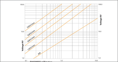
To ensure that the voltage is sufficient to achieve the breakdown of the air but not too high to cause damage thickness bands have been chosen to avoid a single test voltage value being applied to a wide range of thicknesses. If the coating has a relatively high dielectric strength then the selection of the test voltage is less critical as the risk of damaging the coating is much reduced.
For paint systems with a mean dry film thickness of up to 500 μm, low-voltage pinhole detectors shall normally be used. A high-voltage spark tester may, however, be used to test a paint system with a mean dry film thickness of less than 500 μm, but not less than 300 μm, by agreement between the interested parties. For paint systems with a mean dry film thickness greater than 500 μm, high-voltage spark testers shall be used.
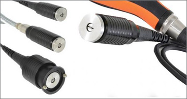
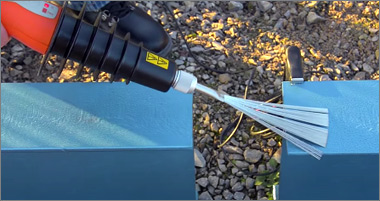
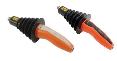
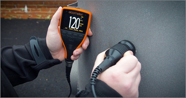
Continuous DC High Voltage Testing requires a signal return cable to be electrically connected between the conductive substrate and the high voltage test unit so that the current that flows from the high voltage electrode when a flaw is detected can flow through the alarm circuit to indicate to the operator that a flaw has been detected. A range of electrode styles has been developed to help the operator apply the voltage to the coated substrate. The electrode supplied as standard is the “Band Brush” probe which is excellent for locating the position of a flaw in the coating. At test voltages above 5 kV the spark can be easily seen and hence the flaw is located. At lower voltages or in bright sunlight the spark might not be so easy to see and the narrow shape of the brush allows the flaw to be located with precision by only applying a small section of the brush in the area of the flaw until it passes over the defect.
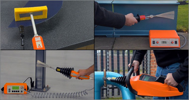
For the design shown in the illustration, the high voltage is generated in the probe handle and the base unit provides the low voltage power supply to the handle from a rechargeable lithium-ion battery, making the unit fully portable. Three different handles are available for different test voltage ranges, 0.5 to 5 kV, 0.5 to 15 kV, and 0.5 to 30 kV. This also helps to prevent over-testing with too high a test voltage. For example, if the coatings to be tested are always less than 1,000 μm (40 mil) thick then the 0.5 to 5 kV handle is the appropriate choice as over-testing at 15 kV or 30 kV would not be possible.
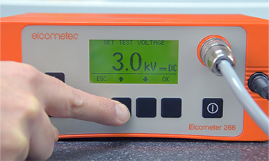
The test voltage can either be set by adjusting the value shown in the base unit display up or down until the selected voltage is displayed or the calculation feature can be used by selecting the standard to which to coating is to be tested from a menu list and then entering the value of the thickness for the coating. The detector will then calculate and set the test voltage based on the standard selected.

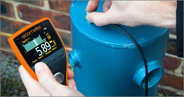
The trailing signal return cable is able to operate because the Pulsed DC test voltage is changing, rising from zero volts to the pre-set test voltage, several kV, 30 times per second. This changing voltage means that a capacitor in the circuit will charge and discharge allowing current to flow. This is not the case with the Continuous DC power supply. A training lead on top of the coating will create a capacitor between the conductive substrate and the un-insulated cable conductor with the insulating coating acting and the dielectric in the capacitor.

For the design shown in the illustration, the high voltage is generated in the probe handle and the base unit provides the low voltage power supply to the handle from a rechargeable lithium-ion battery, making the unit fully portable. Three different handles are available for different test voltage ranges, 0.5 to 5 kV, 0.5 to 15 kV and 0.5 to 30 kV. This also helps to prevent over-testing with too high a test voltage. For example, if the coatings to be tested are always less than 1,000 μm (40 mil) thick then the 0.5 to 5 kV handle is the appropriate choice as over-testing at 15 kV or 30 kV would not be possible.

The test voltage can either be set by adjusting the value shown in the base unit display up or down until the selected voltage is displayed or the calculation feature can be used by selecting the standard to which to coating is to be tested from a menu list and then entering the value of the thickness for the coating. The detector will then calculate and set the test voltage based on the standard selected.

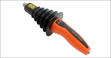
It allows coatings to be tested using a training signal return cable that lies on the surface of the coating and provides a capacitive signal path if a flaw is located by the high voltage electrode.
The trailing signal return cable is able to operate because the Pulsed DC test voltage is changing, rising from zero volts to the pre-set test voltage, several kV, 30 times per second. This changing voltage means that a capacitor in the circuit will charge and discharge allowing current to flow. This is not the case with the Continuous DC power supply. A training lead on top of the coating will create a capacitor between the conductive substrate and the un-insulated cable conductor with the insulating coating acting and the dielectric in the capacitor.


It is also the case that the energy in the Pulsed DC system is contained within the short duration pulses and therefore the test voltage can be maintained on a slightly conductive coating. The system is monitoring for a significant release of energy through a flaw and can ignore the lower energy released by dirt or moisture on the coating. The alarm circuit is set to ignore these stray currents and only react to the significant pulses of energy in the signal return cable.
It should be noted that the capacitive effect that provides the connection through the trailing lead also has an influence on the choice of test electrodes. The capacitive loading of a particular electrode design is affected by the size of the electrode and the thickness of the coating to be tested. In some cases, a large electrode on a thin coating can provide a significant capacitive loading to the pulsed high-voltage power supply making it appear that the electrode is constantly finding flaws. A smaller electrode will normally solve this problem.
Each of the standards, NACE, ASTM and ISO, provide either a method for calculating the test voltage or selecting the test voltage from a table, based on the thickness of the coating to be measured. It must be noted that variations in thickness may cause defects to be detected, either as a result of the coating being too thin and therefore not providing sufficient electrical strength to prevent sparking to the substrate or by causing defects such as runs and sags when the coating is too thick.
Particular care must be taken when the dielectric strength of the coating is low, as too high a test voltage may cause the coating to burn and create a defect where no defect existed before the testing. This has to be managed by careful selection of the test voltage based on detailed knowledge of the coating thickness.
The selection between the Continuous DC and the Pulsed DC method is often one based on practical issues. If the item to be tested has been coated so that not bare metal is available to connect the signal return cable then the Pulsed DC method using the trailing lead signal return is indicated. However, it must be recognized that a good conductive connection is not guaranteed and there is a risk that flaws, particularly small defects may be missed if this method is used.

If the testing is to be carried out at a specific test voltage with high accuracy then the Continuous DC method is indicated as the measurement of a continuous voltage is easier and more accurate than for a pulsed voltage. Again it must be recognized that for reasons of safety in respect of the high voltage the Continuous DC unit has power supplies that reduce the output voltage when current is drawn as it is the flow of current that is dangerous in high voltage testing. To accurately measure the output voltage a very high impedance voltmeter is required so that minimal current is drawn during the test thus keeping the output voltage close to its set value. Once current flows the high voltage test is over and a flaw or defect has been detected. The electrode has to be moved away from the defect to re-establish the test voltage and continue the testing.
There are some differences in the test voltage values given by the different standards and even for the different methods for determining the test voltage within the standards.
For a coating of 500 μm (20 mil) the following voltages are suggested or recommended:
Therefore to avoid over-testing particular coating care must be taken when specifying a high voltage test and the electrical strength of the coating must be taken in to account.